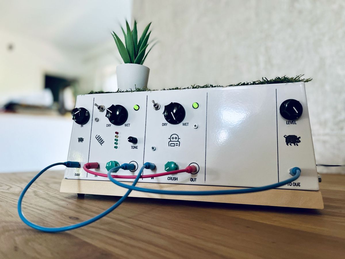
Analog bitcrusher
Bitcrusher with variable downsampling and wet/dry control
Schematics
https://github.com/peterzimon/shmoergh-analog-bitcrusher
References
Relaxation oscillator in CircuitJS simulator
Sample & Hold circuit by Moritz Klein
Active crossfader circuit by Juanito Moore
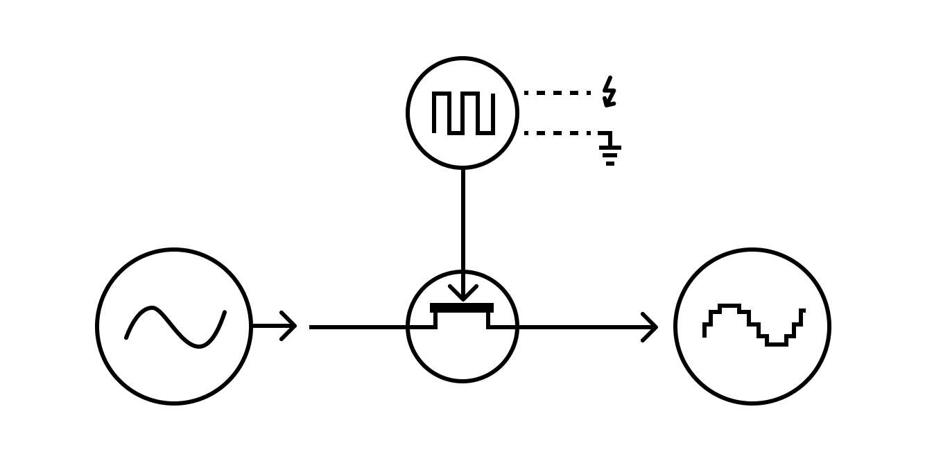
Like with most great things the idea of the bitcrusher is pretty simple. It takes the incoming audio signal and samples it with a fairly low rate.
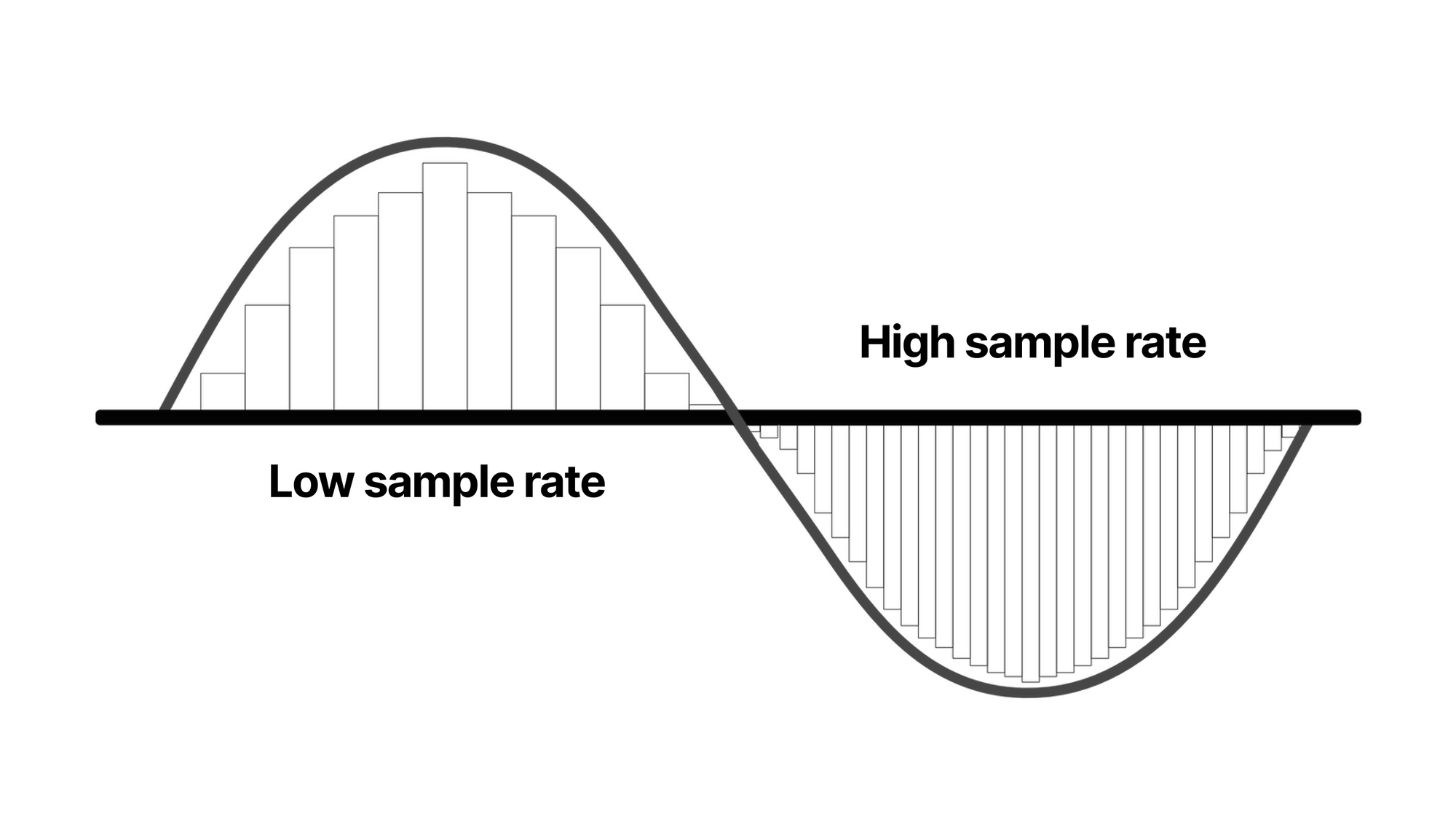
For distortion-free sound the sample rate should be at least twice as fast as of the highest frequency of the signal source, so the digital artifacts (the jumps of the bars in the picture above) can't be heard. That's why the "amazing compact disc" sample rate is 44.1kHz, which it's about half 20kHz max frequency that humans can hear (they can't btw).
The fun starts when you decrease the sample rate and smooth sine waves become stair-like and the robotic sound starts to become more and more obvious.
Bitcrusher plugin in Logic Pro
Achieving this digitally is fairly straighforward since if you want to process any sound you have to sample it first. You just change the sample rate and there you go: you have a bitcrusher. But it's much harder to get to a point of a digital signal processor than doing an analog version of it.
Concept
The theory behind an analog bitcrusher is exactly the same as for digital, the main difference is that sampling happens in an analog signal without any loss in amplitude.
Imagine you have a switch which if you push, it lets the sound through a wire and when you release it, it doesn't. If you could push and release the switch very fast and with a steady tempo then you'd basically make a manual sampler.
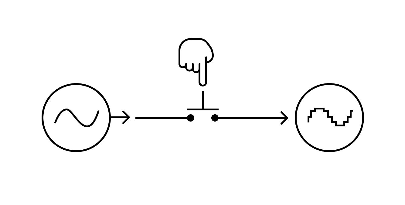
Of course this would be very cumbersome and most probably impossible to do it so we need to automate it. Instead of the humble switch we'll put a humble transistor in the circuit which can be used as an electrically controlled switch: if there's voltage on the gate of the transistor then it lets current flow through it. In our case a BJT wouldn't work for many reasons so we'll go with an n-channel JFET instead.
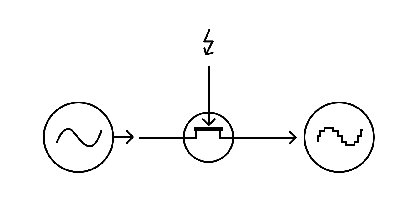
The only thing we need is some sort of periodical signal that turns the transistor on and off, for which we will use a simple relaxation oscillator: a very basic circuit that generates a square wave.
This is of course an over-simplification and it misses some very important bits: most importantly we need to trigger the circuit with very short spikes instead of a regular squarewave and we should hold the sampled voltage until the next sampling period starts.
Circuit details
Sample & hold
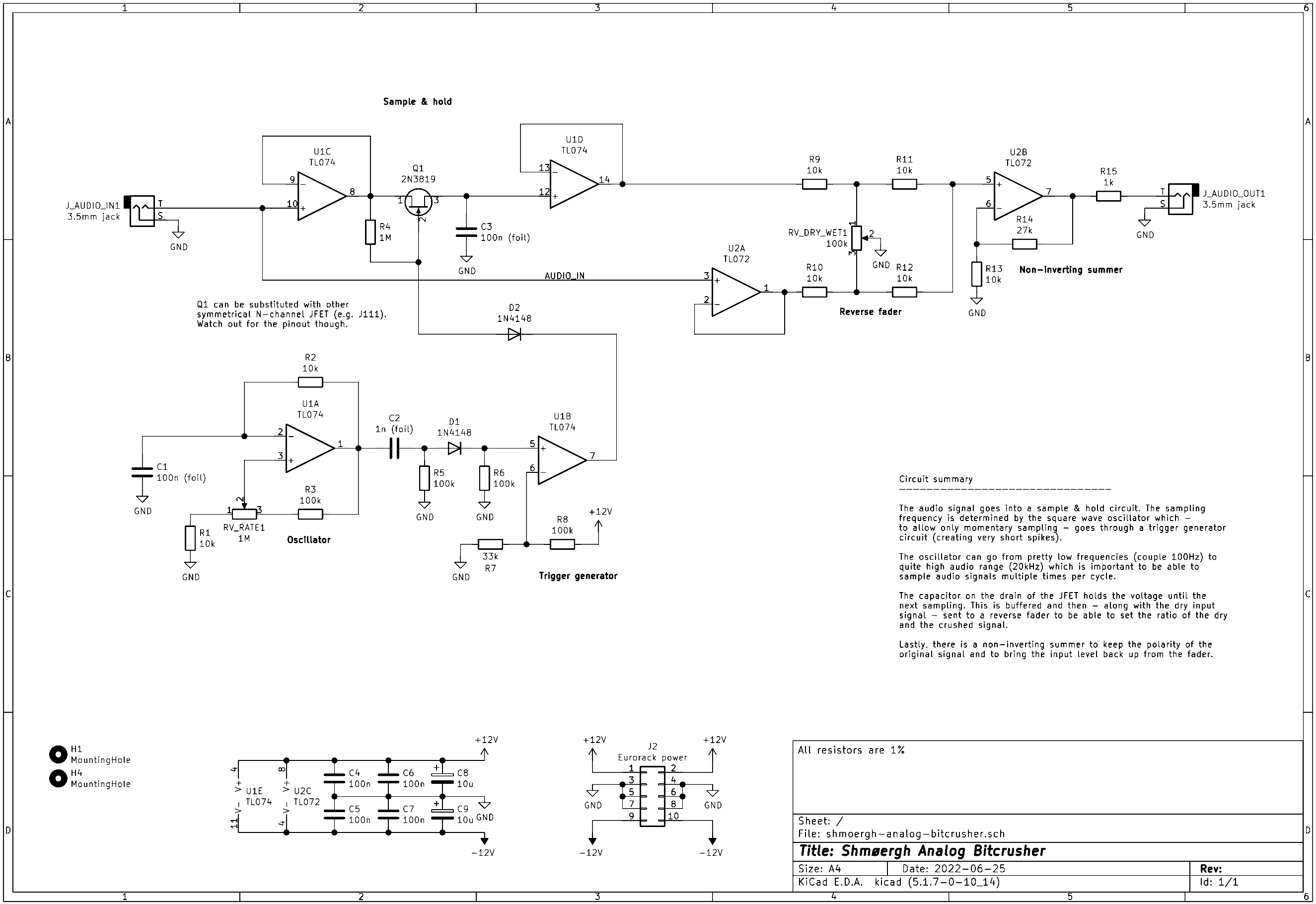
At the bottom there are two mounting holes, decoupling capacitors for the power supply connection and op-amps power pins and a Eurorack power connector. Nothing special for this very circuit.
The audio comes in on the top left into an op-amp set up as a non-inverting buffer which decouples the audio from the source. The signal is driven to probably the most important part, the sample & hold circuit. The two main components here are the n-channel symmetric JFET (a 2N3819 gave me the best results but a J111 or J113 should also work) and a 100n capacitor which holds the voltage for the time the next sampling occurs. If you're interested in how the JFET works with the resistor-diode combination, please watch Moritz Klein's amazing video about it—he explains it way better than I ever could.
The sample & hold circuit is buffered again so that current cannot escape from the 100n capacitor.
The period sampling is made possible via a simple relaxation oscillator (bottom left part of the circuit). There's a 1M potentiometer which allows a wide sampling frequency range that's needed for sampling audio. If you turn the potmeter all the way to the left it samples so fast that the effect is barely audable and as you slow the oscillator down it becomes more and more apparent.
The output of the oscillator is a +/-12V symmetrical squarewave. We can't just connect this signal to open the JFET because we would then sample the signal for the negative portion of each cycle and wouldn't get a nice stair like change in voltage on the output of the JFET.
That's why there's a trigger circuit after the oscillator. It generates very short pulses thanks to the 1n capacitor (C2) and the diode (D1) on the input of a comparator op-amp (again, this is taken from the same video by Moritz Klein—make sure to watch it for further details).
Dry/wet control
The dry/wet control allows mixing the original incoming signal with the distorted, crushed one. It uses a pretty standard subcircuit called the "reverse fader" or "active crossfader". The incoming audio is buffered (decoupled) through an op-amp (U2A) so that the output through the crossfader doesn't interfere with the input. It's connected to one of the legs of a potentiometer (RV_DRY_WET1). The other "input" for the pot is the fully crushed signal which is already buffered. The middle leg of the pot is connected to ground—whichever direction you turn the pot you drive that signal to ground and let the other signal go through to the final output (hence the name "reverse fader").
The output of the dry/wet pot is mixed through an op-amp set up as a non-inverting summer so that the output is again decoupled.